What it does
This original maple-shaped support concept raises a workpiece above the bench, with a single removable spacer for a higher configuration. The geometry is intended to carry replaceable grip pads. Revision 0.2.2 remains a design study because its fastening and wooden fabrication details do not pass review.
Build notes
There is no recorded physical build or test of this revision. Materials, print settings, build time, grip, stability, finish marking and load behaviour remain unqualified. Fabrication instructions and build files are held back until the mechanical defects are corrected and independently reviewed.
The assembled CAD is available for inspection. The exploded mode is withheld because it places the bolt through the bottom pad and the lower locating pins through the spacer.
- Material
- No physical sample recorded. The existing CAD explores wooden and printed construction routes; neither is qualified.
- Print settings
- Layer height: Not recorded; fabrication is withheld.. Walls: Not recorded. Infill: Not recorded; fabrication is withheld.. Orientation: No approved print orientation; fabrication is withheld..
- Tools
- No fabrication tool list is released for this revision.
- Build time
- Not measured; no physical build is recorded.
- Difficulty
- involved
Design notes
What the dimensions establish
The digital low stack adds up: a 28 mm body, a 6 mm foot and two 2 mm pads give 38 mm. Adding one 30 mm spacer gives 68 mm. The rigid footprint is approximately 97.7 × 91.7 mm. These are design dimensions from CAD, not measured prototype results.
The assembled solids have effectively zero interpenetration. That check does not establish whether the fastener can be tightened or the blind sockets can be machined with the proposed tooling.
The fastening arrangement needs a usable tightening path
Both the nominal 10 mm across-flats bolt head and nut sit in 10.5 mm hex pockets. The dowels locate the rigid parts, and both pockets prevent full fastener rotation. The specified sequence supplies no usable final tightening path.
The next revision needs one intentionally rotatable, driveable fastener with room for its actual tool while the other end remains retained. Hardware, pocket geometry, engagement, assembly and servicing need review together. No replacement fastener has been approved.
Wooden sockets need a demonstrated machining method
The wooden foot is 6 mm thick, yet its locating sockets are modelled as 5 mm deep flat-bottom cylinders with 1 mm beneath them. An ordinary pointed drill leaves a different shape. A 118 degree point on a 6.3 mm drill adds approximately 1.893 mm beyond the full-diameter cylinder.
A full 5 mm cylindrical bore would reach approximately 6.893 mm and break through. Stopping the tip sooner changes the usable socket depth and pin seating. A revised foot, socket and pin arrangement, or a demonstrated flat-bottom machining method, is required.
Every model state needs its own check
The old exploded pose put the bolt through the closed bottom pad and, in lifted mode, the lower locating pins through the spacer. Those display defects are separate from assembled fit. The current viewer retains assembled configurations for review and withholds explosion controls.
A corrected revision must pass assembly, tool access, fabrication and every advertised model-state check. Physical prototype trials must then establish grip, stability, finish marking and load behaviour before any working limit is stated.
Explore the actual 3D model
Assembled geometry is shown for design review only. The defective exploded view is withheld. Switch construction routes to inspect the current layout; drag to rotate and use + / − to zoom.
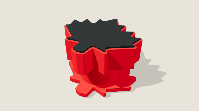
Loading the project model. The CAD preview remains available if 3D cannot start.
Revision history
- 0.2.2 ·
Recorded the independent mechanical review. Withheld fabrication instructions and the defective exploded mode; retained assembled geometry for inspection.